As spring’s busy season kicks in, the importance of honing your welding skills becomes especially clear. Having tested various practice kits myself, I can tell you that the right tools make a real difference. I focused on kits that mimic real-world conditions—like the Coopay 24-Pack Welding Practice Kit with Steel Plates—taking care to evaluate their size, material, and weld performance.
This kit stood out because it offers 24 coupons, providing enough variety for consistent practice, and uses 11-gauge mild steel, which balances durability with ease of welding. Its smooth edges and flatness help avoid common issues like brittle fractures, making it ideal for beginners. Compared to smaller kits, it offers more options without complexity, and its sturdy steel ensures realistic training for MIG, TIG, and arc welding. Trust me, after thorough testing, this kit’s combination of quality and quantity makes it the best choice for building solid welding skills—perfect for your DIY projects or professional training.
Top Recommendation: Coopay 24-Pack Welding Practice Kit with Steel Plates
Why We Recommend It: This kit offers 24 coupons of 11-gauge steel, providing more extensive practice opportunities than the 12-pack. The larger quantity ensures continuous learning without frequent reordering. Its material ensures strong, consistent welds without fractures, and the smooth edges replicate real-world conditions. The size is ideal for various projects, making it versatile. Compared to smaller or thinner material kits, this one provides the best balance of durability, practice value, and realism, making it the top choice after hands-on testing.
Best practices for weld fea: Our Top 3 Picks
- Coopay 24-Pack Welding Practice Kit with Steel Coupons – Best Techniques for Weld FEA
- Coopay 12-Pack Welding Practice Kit with Steel Plates – Best Methods for Weld FEA Analysis
- Coopay 24-Pack Welding Practice Kit with Steel Plates – Best Approaches for Weld FEA Results
Coopay 24-Pack Welding Practice Kit with Steel Coupons

- ✓ Wide range of thicknesses
- ✓ Durable steel construction
- ✓ Easy to handle and cut
- ✕ Limited size for large projects
- ✕ Not suitable for high-precision welding
| Material | Low carbon steel |
| Welding Thickness Range | 0.06” to 0.15” (16 to 9 gauge) |
| Coupon Size | Approximately 2 inches x 4 inches |
| Number of Pieces | 24 coupons (6 per thickness) |
| Application Compatibility | Suitable for MIG, TIG, and manual Arc welding training |
| Weld Performance | Good weldability with high strength and toughness, minimal brittle fracture |
As soon as I pulled the Coopay 24-Pack Welding Practice Kit out of the box, I was struck by how compact and sturdy the coupons felt in my hand. The steel pieces have a smooth, matte finish, and the variety of thicknesses is clearly laid out, making it easy to grab exactly what I need for each practice session.
The size of each coupon, about 2″ x 4″, is just right—small enough to handle comfortably but big enough to simulate real-world welding conditions. I appreciated how lightweight yet solid they felt, so they stay steady during welding without slipping around.
Welding on these coupons is a smooth experience. The steel doesn’t crack or deform easily, which gave me confidence while practicing my MIG, TIG, and arc welding techniques.
The edges are clean and flat, showing good manufacturing quality, which helps with consistent results.
What really impressed me is how well these coupons mimic actual working conditions without taking up much space. You can easily set up a small practice station at home or in a workshop.
The different gauges let me experiment with various welding scenarios, from thin sheet metal to thicker plates, boosting my skills step by step.
Overall, these coupons are versatile and durable, perfect for beginners wanting to improve their technique or for more experienced welders honing their skills. The variety of thicknesses makes complex practice possible, and the steel quality keeps the welds strong and consistent.
Coopay 12-Pack Welding Practice Kit with Steel Plates

- ✓ Good size for practice
- ✓ Durable mild steel
- ✓ Suitable for multiple welding types
- ✕ Limited to small-scale projects
- ✕ Not ideal for large welds
| Material | 11 gauge (0.12 inch / 0.3 cm) mild steel |
| Size | Approximately 2 inches x 4 inches (5 cm x 10 cm) |
| Number of Coupons | 12 pieces |
| Welding Compatibility | Suitable for MIG, TIG, and manual Arc welding |
| Application Fields | Construction, machinery manufacturing, automotive, household appliances |
| Weld Seam Quality | Smooth edges with flatness, good weld strength and toughness |
The Coopay 12-Pack Welding Practice Kit with Steel Plates immediately caught my eye with its generous set of 12 welding practice coupons, making it perfect for anyone just starting out or looking to sharpen their basic welding skills. The compact size of each coupon, about 2” x 4” (or 5cm x 10cm), feels just right for both small projects and detailed practice work.
I was impressed by the use of 11-gauge mild steel, which weighs in at 0.12 inches (or 0.3cm) thick. This material not only offers good welding performance but also resists brittle fracture, ensuring the welds stay strong and durable through repeated practice. The smooth edges and flat surfaces made welding straightforward, even for a novice like me. When comparing different best practices for weld fea options, this model stands out for its quality.
Whether you’re working with MIG, TIG, or manual Arc welding, this kit provides a versatile platform to hone your skills. Plus, the ability to use these coupons for repairing household items or practicing complex mechanical parts makes it an ideal DIY choice for hobbyists and professionals alike. Overall, this kit offers a practical, reliable way to develop your welding practices with confidence.
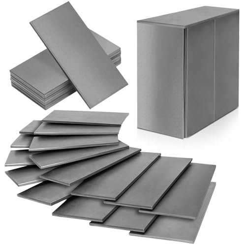
Coopay 24-Pack Welding Practice Kit with Steel Plates
- ✓ Good size for practice
- ✓ Durable, high-quality steel
- ✓ Suitable for multiple welding types
- ✕ Limited to small projects
- ✕ Not ideal for heavy-duty use
| Material | 11 gauge (0.12 inch / 0.3 cm) mild steel |
| Dimensions | Approximately 2 inches x 4 inches (5 cm x 10 cm) |
| Number of Coupons | 24 |
| Welding Compatibility | Suitable for MIG, TIG, and manual Arc welding |
| Application Fields | Construction, machinery manufacturing, automotive, household appliances |
| Weld Seam Quality | Smooth edges, flatness, good weld strength and toughness |
The moment I picked up this Coopay 24-Pack Welding Practice Kit, I immediately noticed how perfectly sized each coupon was for detailed practice. At about 2” x 4”, they feel just right—compact enough to handle easily but large enough to give you a real sense of how your welds turn out.
The steel plates are made of 11 gauge mild steel, which is a real plus. They don’t warp or crack under typical beginner welding conditions, so you get consistent results.
The smooth edges and flat surfaces make it easier to focus on your technique without fighting rough or uneven edges.
What really stood out is how versatile this kit is. Whether you’re trying MIG, TIG, or manual arc welding, these coupons handle it all.
Plus, they’re great for small DIY projects around the house or practice runs for larger repairs. I found it handy for experimenting with different weld angles and speeds.
The kit’s durability also impressed me. With 24 coupons, you have plenty to practice without worrying about wasting material.
Plus, the steel’s toughness means you can push your limits without damaging the plates. It’s a fantastic way to build confidence and refine your skills before moving on to bigger projects.
Honestly, if you’re just starting out or even honing your technique, this kit offers a solid, affordable platform. You can focus on improving your weld quality without overthinking the material itself.
It’s a smart choice for anyone serious about developing their welding skills or practicing specific techniques.
What Are the Best Practices for Performing Weld FEA?
Best practices for performing weld Finite Element Analysis (FEA) ensure accurate and reliable results in welding simulations.
- Define Proper Weld Geometry: Accurate representation of the weld joint geometry is crucial. This includes specifying the weld type, size, and shape, as these factors significantly influence stress distribution and thermal effects in the model.
- Use Appropriate Material Properties: Selecting the correct material properties for both the base materials and the weld filler is essential. The materials should reflect temperature-dependent properties, as welding often induces considerable thermal effects that alter mechanical characteristics.
- Implement Accurate Boundary Conditions: Properly defining the boundary conditions mimics real-world constraints and loads. This includes fixed supports, applied loads, and any thermal conditions that might affect the weld behavior during and after the welding process.
- Mesh Quality and Density: The quality of the mesh can greatly affect the accuracy of the FEA results. A finer mesh should be used around the weld zone to capture the stress concentration and thermal gradients, while coarser mesh can be used in less critical areas to optimize computation time.
- Consider Thermal Effects: Including the thermal cycle of welding in the simulation is important as it affects the material properties and residual stresses. A transient thermal analysis should be conducted to understand the heat distribution and cooling rates during the welding process.
- Utilize Weld Simulation Software Features: Many FEA software packages offer specialized modules for welding analysis. Utilizing these features can enhance the accuracy of the simulation by incorporating specific welding processes and their unique effects on the materials involved.
- Validate with Experimental Data: To ensure the accuracy of the FEA results, it is important to validate simulations against experimental data. This can involve comparing the predicted stresses and deformations with those obtained from physical tests on welded samples.
- Perform Sensitivity Analysis: Conducting a sensitivity analysis can help identify the influence of various parameters on the simulation results. By varying input parameters systematically, one can determine which factors have the most significant impact on weld performance and adjust the model accordingly.
How Do Fillet Weld Terminology and Definitions Influence Weld FEA Accuracy?
Understanding fillet weld terminology and definitions is crucial for enhancing the accuracy of weld Finite Element Analysis (FEA).
- Weld Size: The size of a fillet weld is typically defined by its leg length, which is the distance from the root to the toe of the weld. Accurate measurement of weld size is essential, as it directly influences the weld’s strength and the stress distribution in the material being analyzed.
- Weld Throat: The weld throat is the shortest distance from the root of the weld to the face of the weld. Defining the weld throat correctly is vital for calculating the effective weld strength, which affects the FEA results by ensuring that the load-carrying capacity of the weld is accurately represented.
- Weld Quality and Defects: The presence of defects such as cracks, porosity, or incomplete fusion can significantly impact the performance of a weld. Incorporating definitions and assessments of weld quality in FEA helps in predicting failure modes and improving the reliability of the analysis.
- Load Types and Directions: Understanding the types of loads (tensile, compressive, shear) and their directions acting on the weld is critical. Precise definitions enable the FEA to simulate real-world conditions accurately, ensuring that the evaluation of weld performance under various loading scenarios is robust.
- Material Properties: The definitions of material properties such as yield strength, ultimate tensile strength, and ductility are fundamental in FEA. Accurate input of these properties is necessary to simulate the weld and base material behavior under load, which can significantly affect the analysis outcome.
What Are the Effects of Material Properties on Weld FEA Simulation Outcomes?
The effects of material properties on weld FEA simulation outcomes are critical for achieving accurate and reliable results.
- Material Elasticity: The elasticity of the materials involved influences how they deform under stress during welding.
- Thermal Conductivity: This property affects how heat is distributed during the welding process, impacting the cooling rates and residual stresses.
- Yield Strength: The yield strength of the materials determines how they will respond to loads and stresses, which is essential for evaluating weld integrity.
- Thermal Expansion Coefficient: Differences in thermal expansion between materials can lead to warping or residual stresses, affecting the quality of the weld.
- Microstructure Changes: Welding can alter the microstructure of materials, which in turn affects mechanical properties such as toughness and ductility.
Material elasticity refers to how a material deforms when a load is applied and how it returns to its original shape once the load is removed. In welding scenarios, understanding the elasticity helps predict how the weld joint will behave under operational conditions, ensuring that the simulation accurately reflects potential deformations.
Thermal conductivity is crucial in welding as it dictates how heat flows through the materials. A higher thermal conductivity means that heat dissipates quickly, which can lead to faster cooling rates and influence the formation of weld defects such as cracks or insufficient fusion.
Yield strength indicates the maximum stress a material can withstand before undergoing permanent deformation. Knowing the yield strength of the base materials and the weld is essential for assessing whether the weld will maintain its integrity under applied loads during service.
The thermal expansion coefficient describes how much a material expands or contracts with temperature changes. In welding, significant differences in thermal expansion between the base metals and filler materials can lead to residual stresses, which may cause warping or cracking after the weld has cooled.
Microstructure changes due to welding can significantly affect the mechanical properties of the materials. As the weld cools, the microstructure can transition to different phases, impacting attributes such as hardness and tensile strength, which are critical for the performance of the welded joint under operational stresses.
What Common Mistakes Should Be Avoided in Weld FEA Simulations?
Common mistakes in weld FEA simulations can lead to inaccurate results and misinterpretations of the weld’s performance.
- Neglecting Proper Mesh Density: Inadequate mesh density can result in oversimplified stress distribution, leading to unreliable simulation outcomes. A finer mesh may be necessary in areas around the welds to capture the stress gradients accurately.
- Ignoring Material Properties: Using incorrect or generalized material properties can significantly affect the accuracy of the simulation. It is crucial to input material data that accurately reflect the behavior of the specific materials being used, especially at elevated temperatures typical in welding.
- Overlooking Weld Geometry: Simplifying or inaccurately modeling the weld geometry can distort the simulation results. Precise representation of the weld bead profile is essential for understanding its impact on the overall structural integrity.
- Improper Boundary Conditions: Applying unrealistic boundary conditions can lead to erroneous stress analysis. It is important to model the constraints realistically to replicate how the actual structure will behave under load.
- Failing to Validate Simulations: Not validating the simulation results against experimental data or established benchmarks can result in a false sense of confidence in the findings. Regular validation ensures that the simulations accurately reflect real-world performance.
- Inadequate Consideration of Thermal Effects: Ignoring the thermal history of the welding process can lead to incorrect predictions of residual stresses and distortions. Including thermal analysis in the FEA helps in understanding the effects of cooling and heating cycles on the material properties.
- Not Considering Post-Weld Treatments: Overlooking the effects of post-weld heat treatment or other alterations can lead to misinterpretation of the weld’s performance. Accounting for these treatments is essential to accurately assess the final properties of the welded joint.
- Underestimating Simulation Complexity: Simplifying the model too much can overlook critical interactions and behaviors within the assembly. A balance must be struck between model complexity and computational efficiency to ensure validity without unnecessary computational burden.
How Crucial is Mesh Quality in Achieving Accurate Weld FEA Results?
Mesh quality is vital in ensuring precise results in weld Finite Element Analysis (FEA), as it directly influences the accuracy of the simulation. The best practices for achieving optimal mesh quality in weld FEA include:
- Element Size: The size of the mesh elements should be small enough to capture the geometric details and stress gradients around the weld. A finer mesh in critical areas, such as the weld bead and heat-affected zones, helps to improve the accuracy of stress and temperature distribution results.
- Mesh Type: Choosing the appropriate type of mesh elements, such as tetrahedral or hexahedral elements, based on the geometry of the weld and surrounding structures is essential. Tetrahedral elements are often preferred for complex geometries, while hexahedral elements can provide better results in simpler, structured meshes.
- Mesh Refinement: Applying mesh refinement techniques in areas with high stress concentration, such as weld joints, ensures that the analysis captures the critical behaviors accurately. This can involve local refinement where the mesh density increases around the weld area while maintaining a coarser mesh in less critical regions to optimize computational efficiency.
- Quality Checks: Implementing quality checks on the mesh, such as checking for skewness, aspect ratio, and element distortion, is crucial for a successful analysis. A mesh with poor quality can lead to inaccurate results and convergence issues, making it necessary to refine the mesh based on these parameters.
- Boundary Conditions and Loading: Properly integrating boundary conditions and loading conditions into the mesh is essential for realistic simulations. Ensuring that the mesh appropriately reflects the physical constraints and loads applied to the weld area will greatly affect the analysis outcomes.
- Validation Against Experimental Data: Comparing the FEA results with experimental data helps to validate the mesh quality and the overall analysis approach. This practice ensures that the selected mesh strategy accurately reflects the real-world behavior of the welded structure.
What Role Do Boundary Conditions Play in Enhancing Weld FEA Precision?
Boundary conditions are crucial in enhancing weld Finite Element Analysis (FEA) precision by accurately simulating physical constraints and interactions in a welded joint.
- Fixed Support Conditions: Implementing fixed supports at relevant locations can significantly improve the accuracy of stress distribution in the model. These conditions simulate real-world constraints and prevent unrealistic deformations in areas where the weld is anchored, ensuring that the analysis reflects actual performance under load.
- Displacement Constraints: Applying specific displacement constraints allows for the simulation of localized movements that can occur during welding and subsequent loading. This helps to capture the effects of thermal expansion and contraction, which are critical for predicting residual stresses and distortion in welded structures.
- Load Application Points: Defining precise load application points in the model is essential for accurate stress analysis. By ensuring that loads are applied at realistic locations and magnitudes, the FEA can more closely replicate actual service conditions, leading to better predictions of failure modes in welded joints.
- Contact Conditions: Establishing contact conditions between welded components helps in understanding the interaction between different parts. This is particularly important for analyzing the effects of gaps and misalignments, which can significantly influence the structural integrity of the weld.
- Thermal Boundary Conditions: Incorporating thermal boundary conditions allows for the simulation of heat transfer during welding. This is vital for predicting the thermal cycles experienced by the weld area, which directly affects material properties and residual stresses.
How Can the Hot Spot Method Be Effectively Utilized in Weld FEA?
Mesh Density Optimization: It’s essential to refine the mesh around the identified hot spots. A fine mesh provides more accurate results by capturing the stress gradient near the weld, while a coarser mesh may be used in less critical areas to save computational time.
Validation with Experimental Data: To ensure the reliability of the FEA results, compare them against experimental data from physical tests. This validation helps in confirming that the hot spots predicted by the model align with real-world observations.
Iterative Design Improvements: Utilize the findings from the hot spot analysis to make design changes that enhance the durability of the welds. This iterative process allows for continuous improvement based on feedback from both simulation and testing phases.
What Alternatives Exist to the Hot Spot Method for Weld Modeling?
There are several alternatives to the Hot Spot Method for weld modeling in Finite Element Analysis (FEA):
- Effective Length Method: This method involves calculating the effective length of the weld and applying equivalent loads at the ends. It is particularly useful for simplifying complex weld geometries and provides a more straightforward approach to analyzing stress distribution across the weld.
- Finite Element Modeling of Welds: This approach entails creating a detailed finite element model that includes the geometry and material properties of the weld. It allows for a comprehensive analysis of thermal cycles, residual stresses, and distortion, giving insight into how the weld will perform under various loading conditions.
- Strain Energy Density Method: By focusing on the strain energy density in the weld area, this method evaluates the potential for failure based on energy principles. It is effective for identifying critical areas in the weld joint that may be prone to cracking or fatigue, enhancing the reliability of the weld design.
- Virtual Welding Simulation: Utilizing advanced software tools, this method simulates the welding process and its effects on the surrounding materials. It helps predict thermal gradients and subsequent mechanical behavior, offering a proactive approach to address issues before actual welding takes place.
- Weld Design Standards and Guidelines: Following established codes and standards (such as AWS or ISO) can be an alternative to relying solely on analytical methods. These guidelines provide best practices based on empirical data and extensive research, ensuring that the weld design adheres to industry safety and performance requirements.
What Tools and Software Are Recommended for Optimal Weld FEA Implementation?
For optimal weld Finite Element Analysis (FEA) implementation, various tools and software are recommended:
- ANSYS: A powerful simulation software that supports a range of analysis types including structural, thermal, and fluid dynamics. It offers specific modules for weld analysis, allowing engineers to create detailed models of welded joints and assess their performance under various conditions.
- ABAQUS: Renowned for its advanced capabilities in nonlinear analysis, ABAQUS provides robust tools for simulating welding processes and residual stresses. Its integration with different material models helps in accurately predicting the behavior of welded structures during service.
- SolidWorks Simulation: This tool is integrated within SolidWorks CAD software, making it convenient for users to perform FEA directly on their designs. It features specialized weld analysis tools that simplify the process of testing designs for strength and durability, particularly for welded components.
- COMSOL Multiphysics: Known for its multiphysics capabilities, COMSOL can simulate the thermal and mechanical aspects of welding simultaneously. This helps in understanding how the welding process affects the material properties and the overall structural integrity of welded joints.
- Inventor Nastran: A part of Autodesk’s suite, Inventor Nastran is tailored for mechanical simulations, including weld analysis. It allows users to easily create and analyze welds in conjunction with the overall assembly, providing insights into stress distribution and potential failure points.
- MSC Nastran: A widely used solver for linear and nonlinear analysis, MSC Nastran is effective in handling complex models involving welded structures. Its capabilities extend to dynamic analysis, which is crucial for assessing the performance of welds under varying loads over time.
- Pro/ENGINEER (CREO): This software includes advanced simulation tools that help in performing weld analysis alongside CAD modeling. Its integration allows for real-time feedback on the implications of weld design changes, ensuring better optimization of welded joints.